RPio mockup for scale
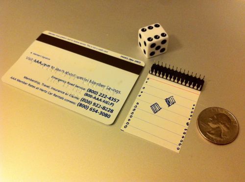
Some reference objects for RPio scale. That’s a credit card (85.60 x 53.98 millimeters), which is the exact size of the Raspberry Pi. Next to it is a piece of card stock cut to the same 53.98-mm length, with the width the same as a 28-pin Atmel ATmega328, which is about 0.1 inches longer than the 26-pin GPIO header on the RPi. In case you couldn’t identify the other items, they’re a die and a U.S. quarter dollar.
Our current board is almost square, but we’re still playing around with the dimensions. It would be interesting to make the RPio stackable like an Arduino shield. The north end could be raw GPIO pinouts, and the bottom pins 5-volt level-shifted with extra 3.3-volt power. I could see many projects being built on those foundations.
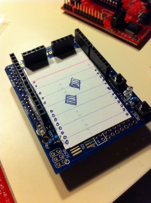
As it happens, the board would fit inside an Arduino proto shield. But I’m not sure why that is useful; unless the RPio’s headers were soldered so that it were plugged in beneath the RPi, it wouldn’t be easy to connect the two at the same time. And I’m having a hard time thinking of a use case where so many I/O pins would need simultaneous connections between an RPi and an RPio.
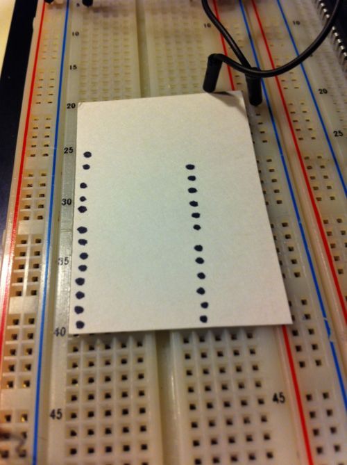
If we moved the headers to be separated by exactly 1.0 inch horizontally, then the board would fit on a standard breadboard with room for a single column of pins on the left. But unless we routed away the board on the right, it would be a hassle to reach the breadboard holes on that side. For some reason, I do see this as slightly more useful than the proto-shield case. You could design a board that plugged in underneath the RPi for certain functions, then it would also plug into the breadboard, maybe for testing, or programming, or diagnostics.