the mostly working circuit in the lower left is
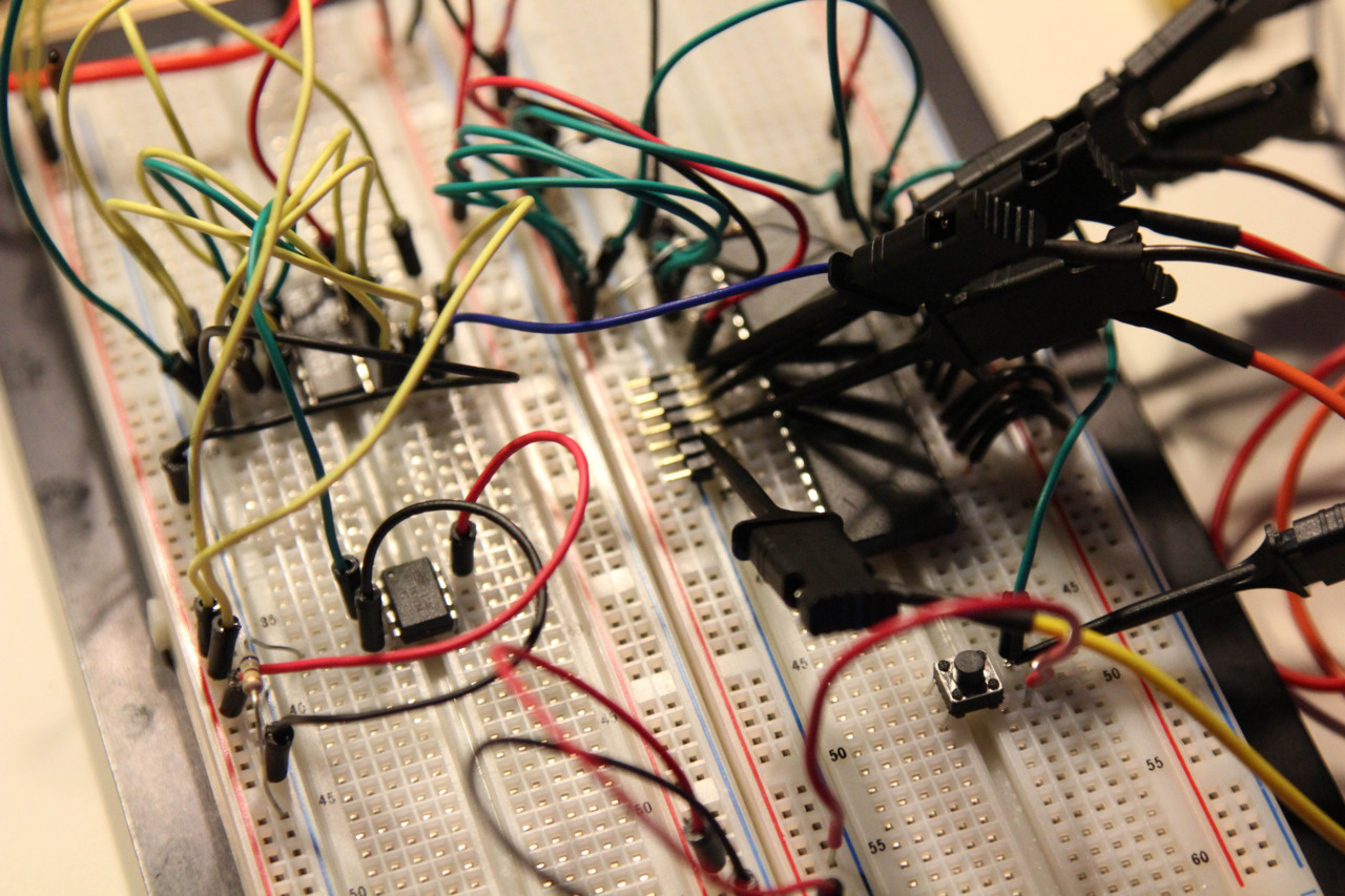
The mostly-working circuit. In the lower-left is the ATtiny13A, running on the 9.6MHz internal RC, and outputting a clock on PB3 as fast as C code can. PB4 is tied to ground because I added a snippet of code to halt the clock when I pressed a button. I then noticed the HALT input on the ‘09, so I will probably remove that functionality from the ‘13A.
In the upper-left is the 74HC109. This is a dual JK positive-edge-trigger flip-flop. That portion of the circuit is adapted from the MC6809E datasheet’s recommendation for generating the weird skewed Q/E clock signals.
And on the right, of course, is the ‘09. It’s gussied up with logic probes, and down at the bottom is a reset button that also happens to provide the rising-edge trigger for the logic probe to start capturing. Under the probes on the right side are the eight data lines hard-coded to $12.