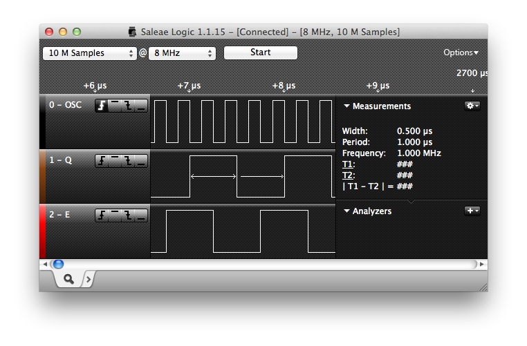
the top screenshot shows a perfect qe clock

Saleae Logic: 1MHz Q/E from 4MHz
clock
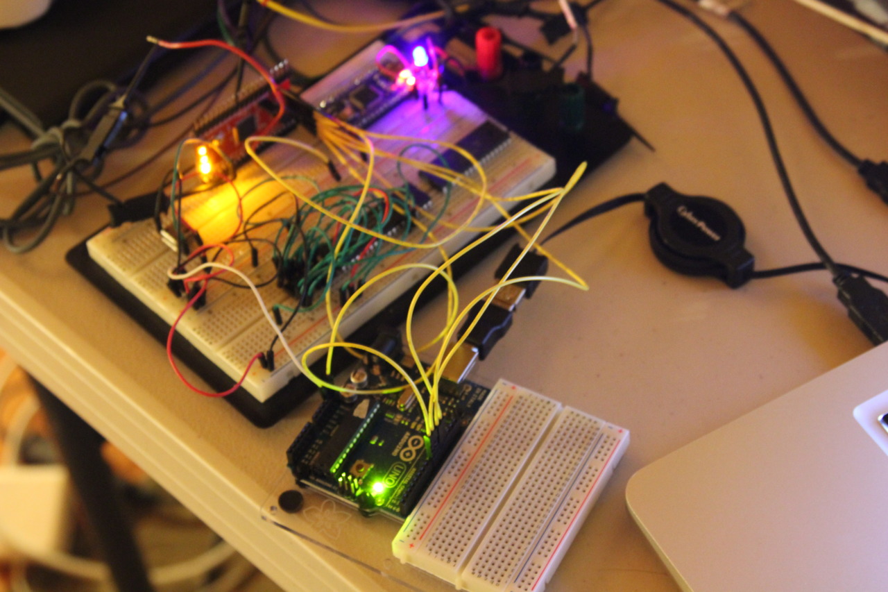
XC9572XL connected to oscillator
The top screenshot shows a perfect Q/E clock signal generated using a 4MHz clock source. No biggie; we’ve seen this before. Right?
The bottom photo shows what’s interesting about this particular clock signal. The XC9572XL is using my very first VHDL that I wrote all by myself, programmed using The JTAG Whisperer! I found a JK flip- flop out on the web, and wired up two of them using the recommended clock circuit in the 6809E datasheet. Synthesized it, generated an XSVF, and pow! It worked!
VHDL is turning out to be exactly as I’d hoped: it’s a text-based schematic entry language. Wire std_logic A to std_logic B, conjure up an imaginary signal here and there, proofread, and then call it all into existence. I’m still finding some parts of the language confusing, and the XSVF step is certainly tedious, but I’m already willing to declare the development process fun.
Code follows.
`entity QE_CLOCK is
Port ( OSC : in STD_LOGIC;
Q_CLK : out STD_LOGIC;
E_CLK : out STD_LOGIC);
end QE_CLOCK;
architecture Behavioral of QE_CLOCK is
component JK_FF_VHDL
port( J,K: in std_logic;
Reset: in std_logic;
Clock_enable: in std_logic;
Clock: in std_logic;
Q, NQ: out std_logic);
end component;
signal ff1_k : std_logic;
signal ff1_nq : std_logic;
signal q_clk_temp : std_logic;
signal e_clk_temp : std_logic;
begin
ff1: JK_FF_VHDL
port map (e_clk_temp, ff1_k, ‘0’, ‘1’, OSC, q_clk_temp, ff1_nq);
ff2: JK_FF_VHDL
port map (q_clk_temp, ff1_nq, ‘0’, ‘1’, OSC, ff1_k, e_clk_temp);
Q_CLK <= q_clk_temp;
E_CLK <= e_clk_temp;
end Behavioral;`