the proof is in the logic analyzer it works rows

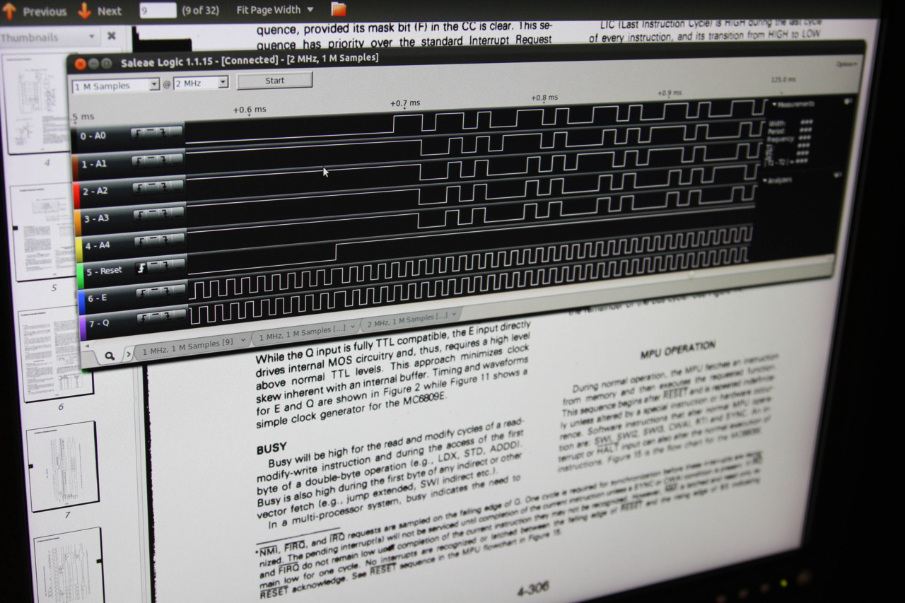
The proof is in the logic analyzer: it works! Rows 0-4 are A0-A4, or the lowest-significance address-bus outputs. Row 5 (green) is the reset signal. The last two rows are the Q/E clocks.
The story this capture tells is exciting! The Q/E clocks are doing their thing. Then reset goes high, telling the processor to grab the address at $FFFE, switch the program counter, and start running. So what I’m actually seeing on the address lines (ignoring A4 so we can work with just the bottom nibble) is E, F, F, 0, 1, F, 0, F, 0, 2, 3, F, 0, F, 0, 4, 5, F, 0, F, 0, 6, 7, F, 0, F, 0… which mostly matches our expectations (more to come in a full post). After I took this photo I figured out that Salae can do the bit-math for me, which is a pretty nice feature.
I believe the reason for the hiccup at the point where reset rises is that the Salae Logic software is running a circular buffer even before it sees the start condition, and because I picked a fairly coarse granularity for sampling (2MHz), it scoots its capturing over a bit to match the rising edge. That’s the only plausible explanation; hitting reset couldn’t possibly affect the clock circuit.